Rack And Pinion Linear Motion Calculation

Diagram Of Rack And Pinion More In Http Mechanical Engg Com Rack Adjustable Table Linear Actuator

Application Of Rack Pinion Mechanism 3 Youtube In 2020 Mechanical Projects Mechanical Design Mechanical Gears
Calculating Rack And Pinion How Do You Do That

Designing Seventh Axis Linear Motion Tracks For Robotic Positioning Diy Cnc Cnc Parts Arduino Cnc

How It S Made A Wooden Reciprocating Rack And Pinion Make Diy Rack Wooden Mechanical Design
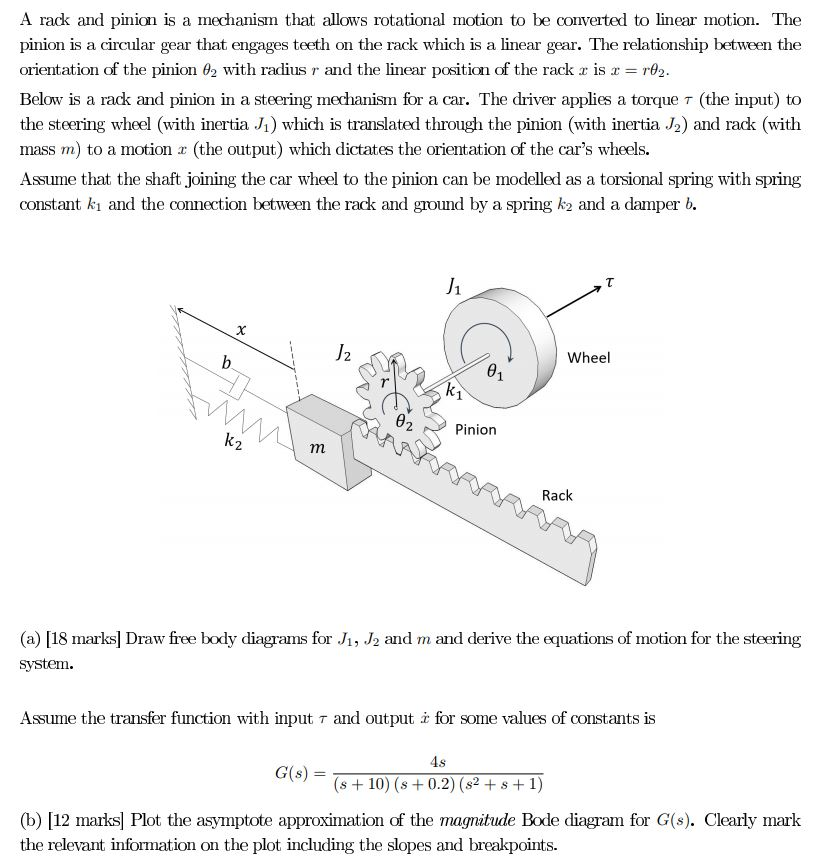
A Rack And Pinion Is A Mechanism That Allows Rotat Chegg Com

The following online calculator computes the basic dimensions and tooth profiles of a meshing rack and pinion based on the pinion s module number of teeth pressure angle usually 20 and profile shift.
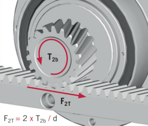
Rack and pinion linear motion calculation.

What Are Rack And Pinion Sets Technical Summary In 2020 Gear Sets Gears Pinion Gear
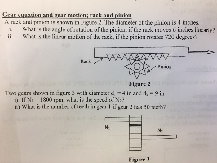
Solved Gear Equation And Gear Motion Rack And Pinion A R Chegg Com

Atlanta Ztrs Highforce Rack Pinion Drive Systems Overview Youtube Diy Cnc Woodworking Garage Diy Lathe

Fusion 360 Rack And Pinion Gear Youtube Pinion Gear Gears Fusion
Source : pinterest.com
