2 9 right handed helical gear important gear terminology and gear nomenclature in fig 2 9.
Rack and pinion gear ratio equation.
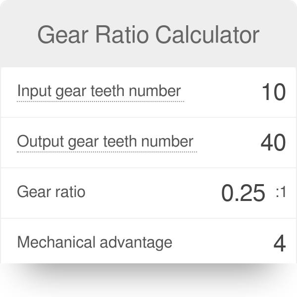
This gear set has pinion with 10 teeth and a gear with 30 teeth.
A simple equation is used to find the ratio of your gearing system number of teeth on the driven gear number of teeth on the drivergear.
The principle is the same but rather than number of rotations the ratio determines the linear distance traveled by the rack with each rotation of the pinion.
A positive profile shift is required for the pinions with 18 teeth or fewer to avoid a collision with the teeth of the rack.
An important principle is that you realize that the calculation and selection rack pinion gearbox and motor is done by trial and error.
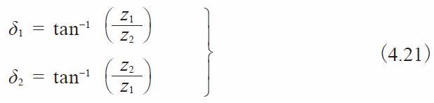
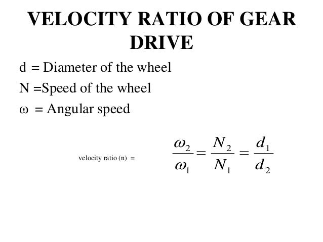
This equation is sometimes simplified as.
Spur gears with helicoid teeth are called helical gears.
The profiles of the rack and pinion can be fully defined by the number of teeth on the pinion module profile shift and pressure angle.
The rotational translational gear constrains the pinion p and rack r to respectively rotate and translate together in a fixed ratio that you specify.
Rack and pinion rack and pinion gears are used to convert rotation from the pinion into linear motion of the rack a perfect example of this.
A rack and pinion gear system consists of a round gear known as the pinion and a flat toothed component known as the rack.
However the gear ratio can still be used to determine the output of a gearbox.
Hardness of the rack.
Example of gear ratio.
The majority of calculations for spur gears can be applied to helical gears too.
Sizing a rack and pinion drive involves calculating the force the rack sees the torque the pinion sees and the rotational speed of the pinion.
You can choose whether the rack axis translates in a positive or negative direction as the pinion rotates in a positive direction by using the rack direction parameter.
This type of gear comes with two kinds of tooth profiles in accordance with the datum surface.
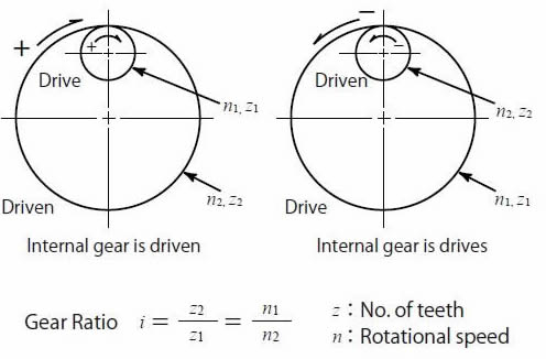
Let s see how this illustration consists of two gear sets.
You have a good chance that you have to do the calculations again with other parameters such as the diameter of the pinion or the quality read in this case.