Rack And Pinion Gear Design Pdf

How To Building Wooden Rack And Pinion Gear Pdf Download Plans Ca Wooden Gears Simple Machines Gears

Stock Illustration Diagram Of A Rack And Pinion Rack Adjustable Table Linear Actuator

Rack Pinion From 507 Mechanisms Animated Automata Whirligig Animation
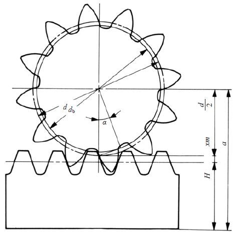
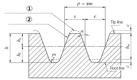
Calculation Of Gear Dimensions Khk Gears

Mechanics And Machine Design Equations And Calculators Engineers Edge Machine Design Gears Mechanic

Rack And Pinion Gear Design Gear Mechanics
Rack and pinion combinations are often used as part of a simple linear actuator where the rotation of a shaft powered by hand or by a motor is converted to linear motion.
Rack and pinion gear design pdf.
Involute Gear Profile Khk Gears
Https Www Jchps Com Specialissues Special 20issue 206 Jchps 2031 20rajasekar 20142 144 Pdf

Inicio Youtube Caladora De Banco Excavadoras

The Everman Belt Drive System When Used With V Slot It Simply Involves Securing By Glue Or Tape A Length Of Timing Belt Inside S Projetos Cnc Cnc Impressao 3d
Source : pinterest.com
